42681fc
LTC4268-1
13
OVERVIEW
Power over Ethernet (PoE) continues to gain popularity
as an increasing number of products are taking advantage
of having DC power and high speed data available from a
single RJ45 connector. As PoE is becoming established in
the marketplace, Powered Device (PD) equipment vendors
are running into the 12.95W power limit established by the
IEEE 802.3af standard. To solve this problem and expand
the application of PoE, the LTC4268-1 breaks the power
barrier by allowing custom PoE applications to deliver up to
35W for power hungry PoE applications such as dual band
access points, RFID readers and PTZ security cameras.
The LTC4268-1 is designed to be a complete solution for
PD applications with power requirements up to 35W. The
LTC4268-1 interfaces with custom Power Sourcing Equip-
ment (PSE) using a high efficiency flyback topology for
maximum power delivery without the need for opto-isolator
feedback. Off-the-shelf high power PSEs are available today
from a variety of vendors for use with the LTC4268-1 to
allow quick implementation of a custom system.
applicaTions inForMaTion
OPERATION
Note: Please refer to the simplified application circuit
(Figure 1) for voltage naming conventions used in this
data sheet.
The LTC4268-1 high power PD interface controller and
switching regulator has several modes of operation depend-
ing on the applied V
PORT
voltage as shown in Figure 2 and
summarized in Table 1. These various modes satisfy the
requirements defined in the IEEE 802.3af specification. The
input voltage is applied to the V
PORTN
pin with reference
to the V
PORTP
pin and is always negative.
SERIES DIODES
The IEEE 802.3af-defined operating modes for a PD refer-
ence the input voltage at the RJ45 connector on the PD.
In this data sheet port voltage is normally referenced to
the pins of the LTC4268-1. Note that the voltage ranges
specified in the LTC4268-1 Electrical Specifications are
referenced with respect to the IC pins.
"
"
16
14
15
1
3
2
RX
6
RX
+
3
TX
2
TX
+
J45
PD FRONT END
SWITCHING REGULATOR
ISOLATED OUTPUT
T1
1
7
8
5
4
11
9
10
6
8
7
TO PHY
V
PORTP
LTC4268-1
V
PORTN
V
NEG
GND
V
CC
PG
SPARE
SPARE
+
V
PORT
V
IN
V
OUT
+
~
~
+
~
~
+
+
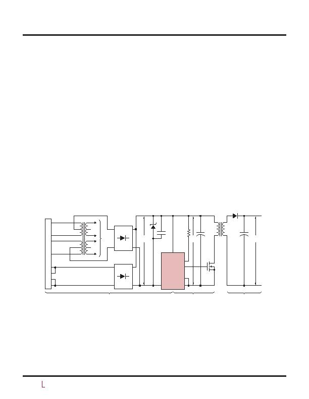
Figure 1. Simplified Application Circuit With Voltage Naming Conventions
发布紧急采购,3分钟左右您将得到回复。
相关PDF资料
LTC4274CUHF#PBF
IC CONTROLLER POE 38-QFN
LTC4280CUFD#PBF
IC CONTROLLER HOT SWAP QFN-24
LTC4300-1IMS8#TRPBF
IC HOTSWAP 2WIRE BUS BUFFR 8MSOP
LTC4300A-2IMS8#TRPBF
IC BUFFER BUS 2WR HOTSWAP 8-MSOP
LTC4301IDD
IC BUFFER BUS HOTSWAP 2WR 8DFN
LTC4301LIDD#TRPBF
IC BUFFER BUS HOTSWAP 2WR 8DFN
LTC4302IMS-1#TRPBF
IC BUFFER 2-WIRE BUS 10-MSOP
LTC4303CDD#TRPBF
IC BUS BUFFER I2C 8-DFN
相关代理商/技术参数
LTC4268IDKD-1#TRPBF
功能描述:IC PD HIGH POWER W/CNTRL 32-DFN RoHS:是 类别:集成电路 (IC) >> PMIC - 热交换 系列:- 产品培训模块:Obsolescence Mitigation Program 标准包装:100 系列:- 类型:热插拔开关 应用:通用 内部开关:是 电流限制:可调 电源电压:9 V ~ 13.2 V 工作温度:-40°C ~ 150°C 安装类型:表面贴装 封装/外壳:10-WFDFN 裸露焊盘 供应商设备封装:10-TDFN-EP(3x3) 包装:管件
LTC4268IDKD-1-PBF
制造商:LINER 制造商全称:Linear Technology 功能描述:High Power PD with Synchronous NoOpto Flyback Controller
LTC4268IDKD-1-TR
制造商:LINER 制造商全称:Linear Technology 功能描述:High Power PD with Synchronous NoOpto Flyback Controller
LTC4268IDKD-1-TRPBF
制造商:LINER 制造商全称:Linear Technology 功能描述:High Power PD with Synchronous NoOpto Flyback Controller
LTC4269-1
制造商:LINER 制造商全称:Linear Technology 功能描述:IEEE 802.3at PD with Synchronous No-Opto Flyback Controller
LTC4269-2
制造商:LINER 制造商全称:Linear Technology 功能描述:IEEE 802.3at High Power PD and Synchronous Forward Controller with AUX Support
LTC4269CDKD-1#PBF
功能描述:IC PD/OPTO FLYBACK CTRLR 32-DFN RoHS:是 类别:集成电路 (IC) >> PMIC - 热交换 系列:- 标准包装:50 系列:- 类型:热交换控制器 应用:-48V 远程电力系统,AdvancedTCA ? 系统,高可用性 内部开关:无 电流限制:可调 电源电压:11.5 V ~ 14.5 V 工作温度:-40°C ~ 85°C 安装类型:表面贴装 封装/外壳:10-TFSOP,10-MSOP(0.118",3.00mm 宽) 供应商设备封装:10-MSOP 包装:管件
LTC4269CDKD-1#TRPBF
功能描述:IC PD/OPTO FLYBACK CTRLR 32-DFN RoHS:是 类别:集成电路 (IC) >> PMIC - 热交换 系列:- 产品培训模块:Obsolescence Mitigation Program 标准包装:100 系列:- 类型:热插拔开关 应用:通用 内部开关:是 电流限制:可调 电源电压:9 V ~ 13.2 V 工作温度:-40°C ~ 150°C 安装类型:表面贴装 封装/外壳:10-WFDFN 裸露焊盘 供应商设备封装:10-TDFN-EP(3x3) 包装:管件
